Icon description
Icon description
Available choices are marked with different symbols (icons) or optic descriptions.
Use of symbols indicates an option within that product group and not that all products have that functionality.
Light sources

LED lamps
With substantial progress of LED technique in the last years today exists new product-specific designed light sources.
DAEYANG as a pioneer for innovative light systems starts with the introduction of the new Lighting this LED technique combined with optimized technique.
LED: Light source of the future
A good example of this is our policy for the testing and selection of LED light sources. Light Emitting Diodes are in rapid development, and the lighting industry is disadvantaged by the lack of international standards. At DAEYANG we aim to produce LED luminaires with single LEDs, LED modules and LED drivers of the best possible quality. For this purpose our test centers are hard at work identifying the components that will provide the most efficient and reliable over time when included in one of our LED luminaires.

5 Year Warranty
DAEYANG warrants for 5 years on the manufacture of all LED products and material defects. This applies to defects if the product is used and installed professionally in accordance with the product data sheet, user manual. Products subject to normal wear and extreme environmental conditions are not covered by the warranty.
* Note: Please contact us for the latest version of the instruction manual and warranty terms.

Fluorescent lamps
The powerful, explosion-protected hand and machine lamps with bi-pin fluorescent lamps fulfill the requirements of ATEX directive 94/9/EC. They are generally suited for use in potentially

Incandescent lamps
These lamps offer much light output because of their high efficiency despite of their small dimensions. They are not very sensitive to vibration and have proved as outdoor floodlights on board of ships. You need a ballast and an igniter. The average lifetime is about 6000 hours.

Sodium lamps
High intensity sodium lamps do not require secondary electrodes. The Xenon gas is ionized with the help of an external starting ignitor that also starts the discharge of sodium vapor. Beyond this starting the operation is as with metal halide lamps.

Halogen lamps
Traditional incandescent lamps lose part of their light intensity in the course of time since tungsten evaporates from the filament and condenses on the inside surface of the bulb forming a dark layer. In modern halogen lamps they prevent this effect by adding halogens to the filling gas. Within the so-called halogen cycle the halogens combine with the evaporated tungsten. This gaseous combination drifting with the heat flow towards the hot filament the tungsten will leave the combination and re-join the filament. The released halogens are again available for the cycle.
Further advantages of halogen lamps:
- Equally bright light throughout life time
- Nice, brilliant light for fresh colors and attractive glamour effects
- Increased light output about 25 % compared with traditional incandescent lamps
- Small dimensions

Xenon
Xenon lamps are DC-operated lamps that are especially suited for applications requiring excellent arc stability and a high luminance. Xenon lamps are short arc lamps in which the discharge arc fires in a pure xenon atmosphere under high pressure. Xenon lamps have a very good color rendering and extremely high luminance. For this reason they are often used in light guide systems, e.g. for endoscopy or dental technology. The Xenon lamps are designed for horizontal burning position, and excel with their compact dimensions. The Xenon lamps are designed for horizontal burning position, and excel with their compact dimensions.

Metal halide lamps
- Positive Environmental Impact
Since metal halide lamps deliver light more efficiently than incandescent, widespread acceptance of the technology has a positive effect on air quality and the environmental waste stream. Lower electrical power generating requirements means less air pollution. Efficient long-life systems mean less landfill waste.
- Wider Range of Applications
Specifiers can now select from a broad variety of lamp types and wattages to suit almost any application. Metal halide lighting is used today indoors and out, for industrial, commercial, retail and municipal spaces. Popular for sports facilities, and site lighting, it is increasingly found in supermarkets, big box retail, offices and lobbies.
Approval

Ex mark, ATEX
The Ex mark is used in addition to the CE mark to indicate products conform to the EN standards for explosive gas atmospheres.
Certificate Number : This consists of the Certifying body’s unique ID code, followed by text “ATEX” followed by a numerical file number

CE mark
The CE mark indicates a product meets all EU directives and conforms to EN standards. This is normally a self certification. Evidenced by a manufacturer’s certification of conformity.

IECEx
The objective of the IECEx System is to facilitate international trade in equipment and services for use in explosive atmospheres, while maintaining the required level of safety: reduced testing and certification costs to manufacturer reduced time to market international confidence in the product assessment process one international database listing maintaining International Confidence in equipment and services covered by IECEx Certification
")
RMRS (Russian Marine Redister of Shipping)
RS quality management system has been certified for compliance with ISO 9001 and verified annually for compliance with IACS QSCS by independent certification body DEKRA. Since 1998 RS has been recognized by the European Union and acting in accordance with the Regulation (EC) 391/2009. RS has been certified by the Entity for the Quality Assessment and Certification of Organizations Recognized by the European Union (QACE).

Korean Register
KR’s class survey regime aims to register the vessels and operate them in a safe and responsible way throughout their service life. KR has also been awarded recognized organization status by a large number of major shipping nation governments.
")
MED (Marine Equipment Directive)
Among the EU Directives is Directive 2014/90/EU of the European Parliament and of the Council on marine equipment. Materials and equipment, covered by this MED and intended to be used on board ships and which are found in compliance with the requirements of the MED, should be affixed with the “Wheel Mark” together with the unique ID number of the certifying Notified Body and should be accompanied by an EC Declaration of Conformity issued by the respective manufacturers.
Standards
 Indicates IP rating
Voltage
Temperature Class
 Zone System
 Recessed Ceiling Type
 Ceiling Type
 Recessed Wall Type
 Wall Type
 Stand Type
 Dimming
 Water Tight
 Low Temperature
 Battery Backup
 Alarm
Alarm
") NVG (Night Vision Goggle)
NVG (Night Vision Goggle)
 ON/OFF switch
 Emergency DC Lamp
Hazardous Area
Hazardous Area

Fire Classification
In order to restrict the spread of fire the bulkheads and decks of a vessel are constructed to a particular standard. Various standards apply depending on the type of vessel and the nature of the space surrounded. Generally the fire resistance of a bulkhead is expressed as A, B or C followed by a number indicating the time that division will prevent a specified temperature rise.
Class "B"
A division capable of preventing the passage of flame the first half an hour of the standard test. The insulation should be such that on the side opposite to a fire the average temperature will not rise more 139 °C above the original temperature nor more than 225 °C at any one point.
Class "B-15" must prevent the stated temperature rises for at least 15 minutes.
Class "B-0" must prevent the stated temperature rises for at least 0 minutes.
A Class "B" division must be constructed of approved non combustible materials except that combustible materials may be permitted provided they meet certain other requirements.
The lighting as a separate unit cannot be fire approved. It is the complete installation with the covering of the installed unit that have to withstand the fire load.
When completing the installation you have to have in mind:
-
Fire rating for ceiling installation
-
The maximum allowed size of recess in the actual ceiling
-
Maximum weight of fixtures/units
-
Minimum allowed distance between recesses
-
Recess construction
-
Method of fixing
-
Type of panels the lighting fixture will be accepted onto: Width and length of panel, Thickness of panel, thickness of steel plate, etc.
The installation on a vessel or a rig will never be exactly as the laboratory test installation. In practice there will be a mixing of cut out for lighting and ventilation as well as ceiling hatches. It is therefore very important to have in mind the minimum allowed distance between recess for the actual ceiling, as well as the maximum allowed load for each ceiling element.
Fire and Explosion Factors
An Explosion can only be taken place, when three factors are present simultaneously

Explosion Limits (LEL, UEL)
Below Lower Explosive Limit : Not enough fuel to ignite
Above Upper Explosive Limit : Not enough oxygen
Between LEL and UEL : Explosive atmosphere

Explosion Limits
| Gases or Vapors |
LEL |
UEL |
| Acetylene |
2,3 |
100 |
| Ethylene |
2,4 |
32,6 |
| Gasoline |
~0,6 |
~8 |
| Methane |
4,4 |
17 |
| Propane |
1,7 |
10,8 |
| Carbon disulphide |
0,6 |
60 |
| Hydrogen |
4,0 |
77 |
Equipment Grouping
Group I Used in mines susceptible to firedamp.
Group II Used in the explosive gas atmosphere.
Group III Used in the explosive dust atmosphere.
IIC can be used in IIB and IIA area.
IIB can be used in IIA area.
IIIC can be used in IIIB and IIIA area.
IIIB can be used in IIIA area.
>Equipment Grouping
| Group |
Gas or Dust |
MESG |
MIC |
Ignition Energy (μJ) |
| I |
Methane |
- |
- |
260 |
| IIA |
Propane |
0,9mm ≤ MESG |
0,8 < MIC |
160 |
| IIB |
Ethylene |
0,5 |
0,45 ≤ MIC ≤ 0,8 |
80 |
| IIC |
Hydrogen, Acetylene |
MESG ≤ 0,5mm |
MIC < 0,45 |
20 |
| IIIA |
Wood, Paper, Cotton Dust |
- |
- |
80 |
| IIIB |
Grain Dust |
- |
- |
| IIIC |
Metal, Coal Dust |
- |
- |
*MESG : Maximum Experimental safe gap
MIC : Minimum Ignition Current Ratio (according to IEC 60079-20-1)
Ignition Energy according to IEC 60079-11. 10.1.5.3

Temperature Class for Group II (Gas or Dust)
Temperature Class for Group II
| Temperature class |
Max. surface temperature [°C] |
Safety margin [K] |
| T1 |
450 |
10 |
| T2 |
300 |
10 |
| T3 |
200 |
5 |
| T4 |
135 |
5 |
| T5 |
100 |
5 |
| T6 |
85 |
5 |
Types of Protection
Types of Protection
| IEC |
Latest Version |
Basic Principle |
Model(DAEYANG) |
Division |
ZONE |
EPL |
| 60079-0 |
Ed. 6
(2011) |
General requirements
This part of IEC 60079 specifies the general requirements for construction, testing and marking of electrical equipment and Ex Components intended for use in explosive atmospheres.
|
|
|
|
|
| 60079-1 |
Ed. 7
(2014) |
Flameproof enclosures “d”
Parts which can ignite a potentially explosive atmosphere are surrounded by an enclosure which withstands the pressure of an explosive mixture exploding inside the enclosure and prevents the transmission of the explosion to the atmosphere surrounding the enclosure.
|
PF-**SBX2 |
Ex da |
0 |
Ga |
| Ex db |
1 |
Gb |
| Ex dc |
2 |
Gc |
| 60079-2 |
Ed. 6
(2014) |
Pressurized enclosures “p”
The formation of a potentially explosive atmosphere inside an enclosure is prevented by maintaining a positive internal pressure of protective gas in relation to the surrounding atmosphere and, where necessary, by supplying the inside of the enclosure with a constant flow of protective gas which dilutes any combustible mixtures.
|
MPS |
Ex pxb |
1/21 |
Gb/Db |
| Ex pyb |
1/21 |
Gb/Db |
| Ex pzc |
2/22 |
Gc/Dc |
| 60079-7 |
Ed. 5
(2015) |
Increased safety “e”
Here additional measures are applied to increase the level of safety, thus preventing the possibility of inadmissibly high temperatures and the occurrence of sparks or electric arcs within the enclosure or on exposed parts of electrical equipment, where such ignition sources would not occur in normal service.
|
EXLED-***ed |
Ex eb |
1 |
Gb |
| Ex ec |
2 |
Gc |
| 60079-11 |
Ed. 6
(2011) |
Intrinsic safety “i”
Equipment that is used in a potentially explosive area only contains intrinsically safe electric circuits. An electric circuit is intrinsically safe if any spark or thermal effect produced under specified test conditions (which include normal operation and specified fault conditions) is not capable of causing ignition of a given explosive atmosphere.
|
- |
Ex ia |
0/20 |
Ga/Da |
| Ex ib |
1/21 |
Gb/Db |
| Ex ic |
2/22 |
Gc/Dc |
| 60079-15 |
Ed. 4
(2010) |
Type of protection “n”
Electrical equipment cannot ignite an explosive atmosphere surrounding it (during normal operation and under defined abnormal operating conditions).
|
EXLED-***ed |
Ex nA |
2 |
Gc |
| Ex nR |
2 |
Gc |
| Ex nC |
2 |
Gc |
| 60079-18 |
Ed. 4
(2014) |
Encapsulation “m”
Parts that are capable of igniting an explosive atmosphere are enclosed in a compound in such a way that ignition of an explosive atmosphere is prevented.
|
EXLED-EMS** |
Ex ma |
0/20 |
Ga/Da |
| Ex mb |
1/21 |
Gb/Db |
| Ex mc |
2/22 |
Gc/Dc |
*EPL Ga can be used in EPL Ga, Gb & Gc ; EPL Gb can be used in EPL Gb & Gc ; EPL Gc can only be used in EPL Gc.
EPL Da can be used in EPL Da, Db & Dc ; EPL Db can be used in EPL Db & Dc ; EPL Dc can only be used in EPL Dc.
*IEC : International Electrotechnical Commission
EPL : Equipment Protection Levels

Zone & EPL (Equipment Protection Level)

Temperature Class for Group II
| |
Zone |
IEC EPL |
Definition |
| Gas |
Zone 0 |
Ga |
A place in which an explosive atmosphere consisting of a mixture with air of dangerous substances in the form of gas, vapor or mist is very likely to occur in normal operation. (>1000 h/y) |
| Zone 1 |
Gb |
A place in which an explosive atmosphere consisting of a mixture with air of dangerous substances in the form of gas, vapor or mist is likely to occur in normal operation. (10~1000 h/y) |
| Zone 2 |
Gc |
A place in which an explosive atmosphere consisting of a mixture with air of dangerous substances in the form of gas, vapor or mist is not likely to occur in normal operation. (<10h/y) |
| Dust |
Zone 20 |
Da |
A place in which an explosive atmosphere in form of a cloud of combustible dust in air is very likely to occur in normal operation. (>1000 h/y) |
| Zone 21 |
Db |
A place in which an explosive atmosphere in form of a cloud of combustible dust in air is likely to occur in normal operation. (10~1000 h/y) |
| Zone 22 |
Dc |
A place in which an explosive atmosphere in form of a cloud of combustible dust in air is not likely to occur in normal operation. (<10 h/y) |
*IEC : International Electrotechnical Commission
EPL : Equipment Protection Levels
IECEx and ATEX
Technically identical standards for electrical equipment since 2006. For single standards, a single set of tests and assessments can support both IECEx and ATEX. An ATEX EC-Type Examination Certificate can be based on an IECEx ExTR but ATEX documentation dose not necessarily support an IECEx certificate.The technical requirements of a manufacturer's QA system are effectively the same, both are based on ISO/IEC 80079-34 and an IECEx QAR can support the issue of an ATEX QAN.

IECEx for the World - Product certification:
- Aim : One single certificate for any hazardous area product recognized and accepted throughout the world.
- Already accepted in many countries. Alternatively a single test report(ExTR) can be sent to any member certification body(ExCB) to issue locally accepted certification.
- Currently only electrical equipment to IEC Standards (but IEC Standards for non-electrical equipment are being developed).
- ExCB issues an ExTR(covering the product type) and a quality assessment report(QAR) (covering the related production facility)
- Certificates of conformity created directly on the IECEx website, fully visible for the whole world to read and check states.
- ExCB maintains the status of certificate based on the outcome of future QARs, a minimum of 2 audit visits in a 3years period.

ATEX for Europe - Conformity Assessment:
- A common approach to lifting barriers to trade within the European Economic Area(EEA).
- The Directive becomes law on implementation in each member country and compliance is mandatory within the EEA.
- Applicable to non-electrical equipment and protective system as well as electrical equipment.
- Certification from a Notified Body is Mandatory for Category 1 and M1 equipment, protective systems and Category 2 and M2 electrical equipment. Otherwise self declaration of compliance is permitted.
- An EC-Type Examination Certificate and Quality Assessment Notification (QAN) are issued by a Notified Body.
- The manufacturer -alone- is responsible for the Declaration of Conformity which must accompany every product which bears the European(CE) Marking.
Installation and maintenance in hazardous areas
Installation and maintenance in accordance with IEC/EN 60079-10, IEC/EN 60079-14, IEC/EN 60079-17.
General requirements ( IEC/EN 60079-14 )
Hazardous areas are classified into Zones 0, 1 and 2 for gases and vapours according to IEC 60079-10-1, and into Zones 20, 21 and 22 for dusts according to IEC 60079-10-2 in order to facilitate the selection of appropriate electrical equipment and the design of suitable electrical installations.
Electrical equipment should, as far as is reasonably practicable, be located in non-hazardous areas. Where it is not possible to do this, it should be located in an area where an explosive atmosphere is least likely to occur. Electrical installations in hazardous areas shall also comply with the appropriate requirements for electrical installations in non-hazardous areas. However the requirements for nonhazardous areas are insufficient for installations in hazardous areas. Where additional protection is required to meet other environmental conditions, for example, protection against ingress of water and resistance to corrosion the method used shall not adversely affect the integrity of the equipment. Electrical equipment and materials shall be installed and used within their electrical ratings for power, voltage, current, frequency, duty and such other characteristics where non-conformity might jeopardize the safety of the installation.In particular, care shall be taken to ensure that the voltage and frequency are appropriate to the supply system with which the equipment is used and that the temperature classification has been established for the correct voltage, frequency and other parameters.
Products for use in hazardous areas are commonly designed for IEC standard voltages according IEC 60038. If a supply voltage is outside of these standardized voltages, then equipment should be specially selected and certified. All electrical equipment and wiring in hazardous areas shall be selected and installed in accordance with Clauses 5 to 13 inclusive and the additional requirements for the particular type of protection (Clauses 14 to 23). Installations should be designed and equipment and materials installed with a view to providing ease of access for inspection and maintenance (IEC 60079-17).
Equipment and systems used in exceptional circumstances, for example research, development, pilot plant where explosion protected equipment is not available, need not meet the requirements of this standard, provided that the installation is under the supervision of a competent body and one or more of the following conditions, as appropriate, are met:
- measures are taken to ensure that an explosiveatmosphere does not occur, or
- measures are taken to ensure that this equipment is disconnected before an explosive atmosphere occurs, in which case ignition after disconnection, e.g. due to heated parts, shall be prevented also; or
- measures are taken to ensure that persons and the environment are not endangered by fires or explosions.
In addition, the measures or conditions or control shall be documented by a competent body who:
- is familiar with the requirements for this, and any other relevant standards and code of practice concerning the use of electrical equipment and systems for use in hazardous areas, and,
- has access to all information necessary to carry out the assessment.

Marking
ATEX Coding

IECEx/ATEX -equipment marking

NVG / NVIS Compatible Lights
NVG / NVIS Compatible Lights

Fire NVG (Night Vision Goggle) Compatible Light
NVG is intended to amplify the minimum amount of light so that objects can be seen at night. However, when the bright light of the luminaries passes through the NVG, it becomes invisible due to the amplification of the light.The NVG filter installed in the NVG compatible light enables the use of NVG by removing the light of the recognized wavelength band of NVG.
The first is to enable the night tactical activities of the NVG users, and the second is to enable the least work of the non-NVG users.
NVG compatible light is required to enable night tactical activities of NVG users and minimal work of non-NVG users.

Classification
Night vision imaging system(NVIS) compatible aircraft interior lighting is divided into the following types and classes.
TYPE I Lighting compatible with any direct view image NVIS utilizing Generation III image intensifier tubes
TYPE II Lighting compatible with any projected image NVIS utilizing Generation III image intensifier tubes.
Class A Lighting compatible with NVIS utilizing 623nm minus blue objective lens filters with the specifications.
Class B Lighting compatible with NVIS utilizing 665nm minus blue objective lens filters with the specifications.
Class C Lighting compatible with NVIS having a ‘green leak’.
This edition of this document assumes that lighting meeting class B compatibility criteria is also compatible with Class C NVIS.
Definition
2-1.Night vision imaging system (NVIS)
Any system that uses image intensifier tubes to produce an enhanced image of a scene in light conditions too low for normal navigation and pilotage.
2-2.Direct view image NVIS (Type I)
Any NVIS that uses generation III image intensifier tubes and displays the intensified image on a phosphor screen in the user’s direct line of sight.
2-3.Projected image NVIS (Type II)
Any NVIS that uses generation III, image intensifier tubes and projects the intensified image on a see through medium in the user’s line of sight. This configuration allows simultaneous viewing of the intensified image and visual cues such as HUD symbology.
2-4.Class A NVIS
Class A NVIS is not compatible with red cockpit lights because of the overlap between the spectrum of red light and the sensitivity of Class A NVIS
2-5.Class B NVIS
A Class B NVIS is compatible with NVIS Red and therefore is compatible with properly filtered red lights and color electronic displays that meet the requirements of Table II,III .
2-6.Class C NVIS
Some aircraft have HUDs that use a hologram as the reflective element in the combining glass. Holograms typically work with only one wavelength of light. This feature can be used to improve the efficiency and see-through clarity of the HUD, but it means the light coming from the HUD is concentrated at one wavelength. since this wavelength is in the green part of the spectrum and is blocked by the minus blue filter in the NVIS, it is nearly impossible to see a holograph HUD with Class A or Class B NVIS. Consequently modified NVIS have been built and tested which have a ‘notch’ or ‘leak’ in the green part of the spectrum The Class C filter is sometimes called the ‘leaky green’filter.
2-7.Compatible interior lighting
The aircraft interior lighting that provides acquisition of aircraft interior information with the unaided eye without degrading the image intensification capabilities of the NVIS during night flight operations. Conforming to the detailed performance and test requirements specified herein shall be considered as meeting this definition
2-8.Secure
An army definition often applied to ground vehicles and equipment meaning that the visible light emitted is reduced to the minimum needed to do the mission and the near IR content is reduced to less than an estimated 5% of the visible light.
2-9.Friendly
Exterior lighting that is fully usable by people without NVIS but has drastically reduced IR content so that it can be used while flying formation with aircraft in which NVIS are being used.
2-10.Covert
IR lights or lights that are typically filtered so they are not visible to the naked eye beyond approximately 20 to 30 feet. These lights may be intended to provide illumination so that NVIS will work without adequate natural light.
Relative spectral response characteristics of Class A,B,C NVIS
This document defines the radiant energy interface requirements and test procedures applicable to NVIS compatible lighting systems for new or modified aircraft lighting equipment and crew stations. Figure is the assumed NVIS spectral response characteristics that shall be used to define NVIS compatibility criteria herein.
Relative spectral response characteristics of Classes A, B and C NVIS
NVIS lighting color limits
The color of illuminated information on instruments, control, control panels, and on illuminated areas in designated crew station and compartment areas shall be as specified herein for that component. These lighting colors and limits are shown on the chromaticity diagram and are designated as ‘NIVS GREEN A’, ’NVIS GREEN B’, ’NVIS YELLOW’, ‘NVIS RED’, ’NVIS WHITE’
Conformance to these colors and color limits is determinated by the following formula(u’- u1)2 + (v’- v1)2 ≤( r ) 2
where ;u’and v’ = 1976 UCS chromaticity coordinates of the test article
u1’ and v1’= 1976 UCS chromaticity coordinates of the center point of the specified color area
r = radius of the allowable circular area on the 1976 UCS chromaticity diagram for the specified color

CIE 1976 UCS Chromaticity Diagram
NVG compatible and incompatible lighting relative to the NVG response
A complication is the existence of different ‘classes’ of NVG, which refers to the exact response bands of the devices. Class A NVGs have a response that starts at around 625nm and extends to about 930nm, while Class B NVGs respond in the range 655nm to 930nm.
These wavelengths are controlled by the use of special filters, often referred to as ‘ minus blue’ filters, mounted on the front of the NVGs.

NVG compatible green & red lighting and Class A & B NVG response
One effect of this is that it is harder to make lighting compatible with Class A NVGs than Class B.
Indeed red lighting can not be used successfully in a cockpit with Class A NVGs.
MIL-STD-3009 takes account of these two classes in defining colors and levels of compatibility.
They relative responses of Class A and Class B NVGs, with NVG compatible green and red light outputs superimposed.

NVG compatible & NVG friendly light relative to NVG response
Whereas internal lighting is generally required to be very compatible, with negligible impact on NVGs, external lighting needs Lighting needs to be visible, both through NVGs and to the naked eye, in order to perform its intended function of providing awareness of position and direction of flight.
This means there has to be a greater degree of overlap between the emissions and the NVG response, but not so much that the NVGs are degraded -a balance is required where an NVG friendly light output is compared with an NVG compatible source, relative to the Class B NVGs response

MIL-STD-3009
TABLE III. NVIS radiance requirements(metric units)
TABLE III. NVIS radiance requirements
| |
|
|
TYPE1 |
TYPE2 |
| Lighting components |
|
Paragraph |
Class A |
Class B |
Class A |
Class B |
| |
|
|
Not Less Than :
(nNRA) |
Not Greater
Than :
(nNRA) |
cd/m² |
Not Less Than :
(nNRB)
|
Not Greater
Than :
(nNRA) |
cd/m² |
Not Less Than :
(nNRA) |
Not Greater
Than :
(nNRA) |
cd/m² |
Not Less Than :
(nNRA) |
Not Greater
Than :
(nNRA) |
cd/m² |
| Primary |
|
4.3.5.1 |
--- |
0.17 |
0.343 |
1/ Same as Class A |
--- |
0.17 |
0.343 |
1/ Same as Class A |
| Secondary |
|
4.3.5.2 |
--- |
0.17 |
0.343 |
--- |
0.17 |
0.343 |
| Illuminated controls |
|
4.3.5.3 |
--- |
0.17 |
0.343 |
--- |
0.17 |
0.343 |
| Compartment |
|
4.3.5.4 |
--- |
0.17 |
0.343 |
--- |
0.17 |
0.343 |
Utility, map, work and
inspection lights |
Green |
4.3.5.5 |
--- |
0.17 |
0.343 |
--- |
0.17 |
0.343 |
| White |
4.3.5.5 |
--- |
1.0 |
0.343 |
--- |
1.0 |
0.343 |
| Caution and advisory lights |
|
4.3.5.6 |
--- |
0.17 |
0.343 |
--- |
0.17 |
0.343 |
|
|
|
| Jump lights |
|
4.3.5.7 |
17.1 |
50 |
17.1 |
16 |
47 |
17.1 |
--- |
50 |
17.1 |
--- |
47 |
17.1 |
| Warning signal |
|
4.3.5.8 |
50 |
150 |
51.5 |
47 |
140 |
51.5 |
--- |
150 |
51.5 |
--- |
140 |
51.5 |
| Master caution signal |
|
4.3.5.8 |
50 |
150 |
51.5 |
47 |
140 |
51.5 |
--- |
150 |
51.5 |
--- |
140 |
51.5 |
| Emergency exit lighting |
|
|
50 |
150 |
51.5 |
47 |
140 |
51.5 |
--- |
150 |
51.5 |
--- |
140 |
51.5 |
Electronic and electro-
optical displays
(monochromatic) |
|
|
--- |
0.17 |
1.71 |
--- |
0.16 |
1.71 |
--- |
0.17 |
1.71 |
--- |
0.16 |
1.71 |
|
Electronic and electro-optical displays
(multi-color)
|
White |
|
--- |
2.3 |
1.71 |
--- |
2.2 |
1.71 |
--- |
2.3 |
1.71 |
--- |
2.2 |
1.71 |
| MAX |
|
--- |
12 |
1.71 |
--- |
11 |
1.71 |
--- |
12 |
1.71 |
--- |
11 |
1.71 |
| HUD systems |
|
4.3.5.10 |
1.71 |
5.1 |
1.71 |
1.6 |
4.7 |
17.1 |
--- |
17 |
1.71 |
--- |
1.6 |
1.71 |
Where :
nNRA = nano NVIS radiance requirements for Class A equipment.
nNRB = nano NVIS radiance requirements for Class B equipment.
“nano”. abbreviated “n”. represents a factor of 10-9. which is factored out of the radiance numbers in this table.
cd/m² = Candela per square meter. sometimes called “nits”.
NOTE1. For these lighting components. Class B equipment shall meet all Class A requirements of this specification.
The relative NVIS response data for Class A equipment. GA(λ) (TABLE III.a.). shall be substituted for GB(λ) to calculate NVIS radiance.
TABLE III.a. NVIS radiance requirements using English units
TABLE III.a. NVIS radiance requirements
| |
|
|
TYPE1 |
TYPE2 |
| Lighting components |
|
Paragraph |
Class A |
Class B |
Class A |
Class B |
| |
|
|
Not Less Than :
(nNRa) |
Not Greater
Than :
(nNRa) |
fl |
Not Less Than :
(nNRb)
|
Not Greater
Than :
(nNRa) |
fl |
Not Less Than :
(nNRa) |
Not Greater
Than :
(nNRa) |
fl |
Not Less Than :
(nNRa) |
Not Greater
Than :
(nNRa) |
fl |
| Primary |
|
4.3.5.1 |
--- |
1.7 x 10-¹º |
0.1 |
1/ Same as Class A |
--- |
1.7 x 10-¹º |
0.1 |
1/ Same as Class A |
| Secondary |
|
4.3.5.2 |
--- |
1.7 x 10-¹º |
0.1 |
--- |
1.7 x 10-¹º |
0.1 |
| Illuminated controls |
|
4.3.5.3 |
--- |
1.7 x 10-¹º |
0.1 |
--- |
1.7 x 10-¹º |
0.1 |
| Compartment |
|
4.3.5.4 |
--- |
1.7 x 10-¹º |
0.1 |
--- |
1.7 x 10-¹º |
0.1 |
| Utility, map, work and inspection lights |
Green |
4.3.5.5 |
--- |
1.7 x 10-¹º |
0.1 |
--- |
1.7 x 10-¹º |
0.1 |
| Primary |
White |
4.3.5.5 |
--- |
1.7 x 10-¹º |
0.1 |
--- |
1.0 x 10⁻⁹ |
0.1 |
| Caution and advisory lights |
|
4.3.5.6 |
--- |
1.7 x 10-¹º |
0.1 |
--- |
1.7 x 10-¹º |
0.1 |
| Jump lights |
|
4.3.5.7 |
1.7 x 10-⁸ |
5.0 x 10-⁸ |
5.00 |
1.6 x 10-⁸ |
4.7 x 10-⁸ |
5.0 |
--- |
5.0 x 10-⁸ |
5.0 |
--- |
4.7 x 10-⁸ |
5.0 |
| Warning signal |
|
4.3.5.8 |
5.0 x 10-⁸ |
1.5 x 10-⁷ |
15.0 |
4.7 x 10-⁸ |
1.4 x 10-⁷ |
15.0 |
--- |
1.5 x 10-⁷ |
15.0 |
--- |
1.4 x 10-⁷ |
15.0 |
| Master caution signal |
|
4.3.5.8 |
5.0 x 10-⁸ |
1.5 x 10-⁷ |
15.0 |
4.7 x 10-⁸ |
1.4 x 10-⁷ |
15.0 |
--- |
1.5 x 10-⁷ |
15.0 |
--- |
1.4 x 10-⁷ |
15.0 |
| Emergency exit lighting |
|
|
5.0 x 10-⁸ |
1.5 x 10-⁷ |
15.0 |
4.7 x 10-⁸ |
1.4 x 10-⁷ |
15.0 |
--- |
1.5 x 10-⁷ |
15.0 |
--- |
1.4 x 10-⁷ |
15.0 |
Electronic and electro-
optical displays
(monochromatic) |
|
|
--- |
1.7 x 10-¹º |
0.5 |
--- |
1.6 x 10-¹º |
0.5 |
--- |
1.7 x 10-¹º |
0.5 |
--- |
1.6 x 10-¹º |
0.5 |
|
Electronic and electro-optical displays
(multi-color)
|
White |
|
--- |
2.3 x 10⁻⁹ |
0.5 |
--- |
2.2 x 10⁻⁹ |
0.5 |
--- |
2.3 x 10⁻⁹ |
0.5 |
--- |
2.2 x 10⁻⁹ |
0.5 |
| MAX |
|
--- |
1.2 x 10-⁸ |
0.5 |
--- |
1.1 x 10-⁸ |
0.5 |
--- |
1.2 x 10-⁸ |
0.5 |
--- |
1.1 x 10-⁸ |
0.5 |
| HUD systems |
|
4.3.5.10 |
5.1 x 10⁻⁹ |
5.1 x 10⁻⁹ |
5.0 |
1.6 x 10⁻⁹ |
4.7 x 10⁻⁹ |
5.0 |
--- |
1.7 x 10⁻⁹ |
5.0 |
--- |
1.6 x 10⁻⁹ |
5.0 |
Where :
NRa = NVIS radiance requirements for Class A equipment.
NRb = NVIS radiance requirements for Class B equipment.
fL = footlamberts
NOTE1. For these lighting components, Class B equipment shall meet all Class A requirements of this specification.
The relative NVIS response data for Class A equipment. Ga(λ) (TABLE III.a.). shall be substituted for Gb(λ) to calculate NVIS radiance.
IP and IK Classification
IP and IK Classification
IP CLASS
IP (Ingress Protection) classification tells us the product capability to avoid ingress from water or solid objects. The first number refers to solid objects/dust and the second to water. DAEYANG has laboratories for testing IP classification. Mainly, higher IP-rating means higher dust and watertightness.
If one or both numerals are stated as "X", the product could not be subjected to the relevant test. The statement "X" cannot, however, be used to signify any random IP rating.
IP protection degrees for enclosures
Degrees of protection against solid foreign objected by the first characteristic numeral.
First characteristic numeral : Protection against solid bodies
First characteristic numeral : Protection against solid bodies
| IP |
Tests |
Description |
Definition |
| 0 |

|
Non-protected |
- |
| 1 |

|
Protected against solid foreign objects of50mm diameter and greater(accidental contact with the hand) |
The object probe, sphere of 50mm diameter,shall not fully penetrate(The full diameter of the object probe shall not pass through an opening of the enclosure.) |
| 2 |

|
Protected against solid foreign objects of12.5mm diameter and greater(finger of the hand) |
The object probe, sphere of 12.5mm diameter,shall not fully penetrate(The full diameter of the object probe shall not pass through an opening of the enclosure.) |
| 3 |

|
Protected against solid foreign objects of2.5mm diameter and greater(tools, wires) |
The object probe of 2.5mm diametershall not penetrate at all(The full diameter of the object probe shall not pass through an opening of the enclosure.) |
| 4 |

|
Protected against solid foreign objects of1mm diameter and greater(fine tools, small wires) |
The object probe of 1mm diametershall not penetrate at all(The full diameter of the object probe shall not pass through an opening of the enclosure.) |
| 5 |

|
Dust-Protected(no harmful deposit) |
Ingress of dust is not totally prevented, but dust shallnot penetrate in a quantity to interfere with satisfactoryoperation of the apparatus or to impair safety |
| 6 |

|
Dust-tight |
No ingress of dust |
Second characteristic numeral : Protection against liquids
Second characteristic numeral : Protection against liquids
| IP |
Tests |
Description |
Definition |
| 0 |

|
Non-protected |
- |
| 1 |

|
Protected against verticallyfalling water drops |
Vertically falling drops shall have no harmful effects |
| 2 |

|
Protected against verticallyfalling water dropswhen enclosure tilted up to 15° |
Vertically falling drops shall have no harmful effectswhen the enclosure is tilted at any angle up to 15°on either side of the vertical |
| 3 |

|
Protected against spraying water |
Water sprayed at an angle up to 60° on either side ofthe vertical shall have no harmful effects |
| 4 |

|
Protected against splashing water |
Water splashed against the enclosure from anydirection shall have no harmful effects |
| 5 |

|
Protected against water jets |
Water protected in jets against the enclosure from anydirection shall have no harmful effects |
| 6 |

|
Protected against power water jets |
Water protected in powerful jets against the enclosurefrom any direction shall have no harmful effects |
| 7 |
|
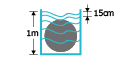
Protected against the effects oftemporary immersion in water |
Ingress of water in quantities causing harmful effects shall not be possible when the enclosure is temporarily immersed in water under standardized conditions of pressure and time |
| 8 |
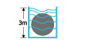
|
Protected against the effects oftemporary immersion in water |
Ingress of water in quantities causing harmful effects shall not be possible when the enclosure is temporarily immersed in water under standardized conditions of pressure and time |
Cleaning processes carried out professionals are not covered by the IP rating data. If necessary, manufacturers are advised to provide relevant cleaning process information.
This is in accordance with the recommendations on professionally executed cleaning processes as stated in IEC 60529.
IK Number
This standard refers to the classification of the degrees of protection provided by enclosures against external mechanical impacts when the rated voltage of the protected equipment is not greater than 72,5 kV.This standard is only applicable to enclosures of equipment where the specific standard establishes degrees of protection of the enclosure against mechanical impacts.
IK Number
| IK |
Tests |
Impact Energy (joules) |
Equivalent Impact |
| 0 |

|
Non-protected |
No Test |
| 1 |

|
0.15 |
Drop of 200g object from 7.5cm height |
| 2 |

|
0.2 |
Drop of 200g object from 10cm height |
| 3 |

|
0.35 |
Drop of 200g object from 17.5cm height |
| 4 |

|
0.5 |
Drop of 200g object from 25cm height |
| 5 |

|
0.7 |
Drop of 200g object from 35cm height |
| 6 |

|
2 |
Drop of 500g object from 20cm height |
| 7 |

|
3 |
Drop of 500g object from 40cm height |
| 8 |

|
5 |
Drop of 1.7kg object from 29.5cm height |
| 9 |

|
10 |
Drop of 5kg object from 20cm height |
| 10 |

|
20 |
Drop of 5kg object from 40cm height |